
Compact AC/DC and DC/DC power modules covering the low-voltage auxiliary supply nodes of AC wallboxes, public AC chargers, DC fast chargers and station-level systems — from wide-input mains conversion to isolated communications, logic rails and station-level auxiliary power.
Control, communication, metering, safety detection, HMI, payment, locks and thermal management require a low-voltage auxiliary power tree. Modest power, continuous operation and certification sensitivity. An auxiliary-supply failure directly affects charger availability.
Controller, communication, metering, lock control, LED / small display. Few nodes per unit; platform projects offer volume.
Controller, OCPP communication, metering, payment, HMI, locks, safety detection. Certification, low-temperature operation, EMC and serviceability matter more.
Control, billing, communication, insulation monitoring, contactors, fan / thermal-management control. Independent of the main charging conversion stage.
Dispenser cabinet, power-cabinet control boards, station cabinet, EMS, communication gateway. Expand from a single AC/DC module to a complete power-tree offering.
85–305 VAC operating range, covering 120/230/277 VAC single-phase grids.
3 kVDC isolated DC/DC for communication, detection and sampling isolation.
OVC III + Class B for surge immunity and low-temperature outdoor environments.
Always-on, availability-first, matching charger operations.
Power rating alone does not define the requirement. Input disturbances, fixed installation and OVC, EMC, outdoor cold and high altitude, shared low-voltage loads, power-to-control isolation and operational availability must all be assessed together.
Input range, surge levels and front-end protection must be assessed together — not nominal voltage alone.
Covers 120/230/277 VAC single-phase grids.Public and commercial equipment sits in more demanding distribution environments, with higher overvoltage-category requirements.
OVC III + PD3 with fewer external circuits.Chargers carry multiple communication and metering-sensitive circuits; failed end-product certification causes rework and delay.
Class B without external circuitry.−40 °C start-up, temperature rise and derating directly affect North American, northern European and high-altitude projects.
−40 to +85 °C, 5000 m altitude.Coincident peaks from HMI, communication, payment, relays and fans cannot be sized on average consumption alone.
Plan continuous loads at 70–85% of rating.Typical architectures show how AC/DC, isolated DC/DC and non-isolated DC/DC modules support the different power domains inside a charger.
Figure 1. Typical 12 V intermediate-bus architecture (AC charger). Actual bus voltage and isolation requirements depend on the charger design; the complete input protection and EMC network should be evaluated together with the selected AC/DC module.
Figure 2. Typical 24 V auxiliary-bus architecture (DC fast charger). The main charging energy path stays outside the PMR module; reverse-feed risk on the low-voltage auxiliary bus must be assessed during project evaluation.
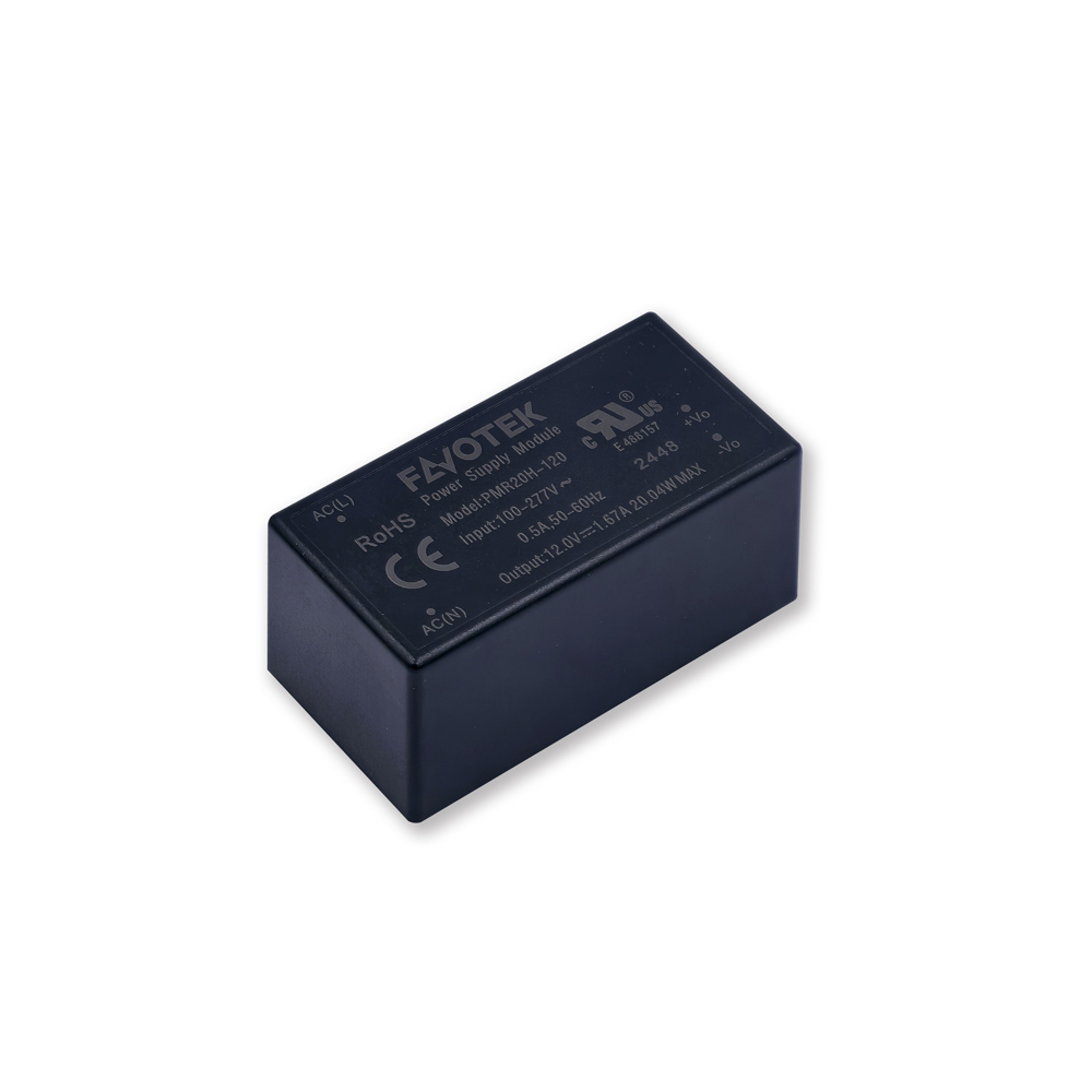
A 20 W encapsulated AC/DC platform — OVC III + PD3, Class B without external circuitry, −40 to +85 °C for outdoor use. The standard evaluation entry for public AC chargers and 12 V / 20 W auxiliary supply.
A coordinated portfolio for mains conversion, low-voltage rails and isolated auxiliary power.
| Power Function | Series | Key Specifications | Typical Application |
|---|---|---|---|
| Encapsulated AC/DC | PMR | 15–60 W · 85–305 VAC · 4000/4200 VAC | Main charger auxiliary-supply entry (OVC III; PD3 on select models) |
| Phase-to-phase AC/DC | PMW | 30 W (preliminary) · 176–528 VAC · 4000 VAC | 480/528 VAC phase-to-phase extension |
| Open-frame AC/DC | PNR · PNW | 3–15 W / 5–10 W · 85–305 / 90–528 VAC · 4000 VAC | Customer-designed mechanics and cooling |
| Isolated DC/DC | MEK · MRK | 3 kVDC · unregulated / regulated | Comms, detection and sampling isolation |
| Non-isolated step-down | RM · RN | 1–2 A · 24/15 V → 5/3.3 V | Local point-of-load (POL) rails |
| Station-level DC/DC | MU · MV | 4:1 / 2:1 · 1.6 kVDC | Station cabinets, EMS and gateways at 24/48 V |
| Gate-drive DC/DC | MQ | 5000 VAC · CMTI > 200 kV/µs | IGBT drive inside main power modules |
The table maps representative families to charger power domains. Contact FAVOTEK to confirm full part numbers, output options and certification status.
Power platforms, engineering support and supply capability for always-on EVSE control, communication, metering and safety-detection nodes. 3-year warranty · designed for continuous operation.
Encapsulated AC/DC at 5 W and above with OVC III + PD3 is scarce; PMR15H / 20H / 90H cover the 15 / 20 / 90 W steps.
Auxiliary power is independent of the main charging conversion; control and communication stay online in standby, fault and maintenance states.
Offline communication, failed payment or lock faults take the whole charger out of service; industrial modular supplies reduce field-failure risk.
Module-level safety, EMC and reliability documentation; end-product certification remains subject to actual system validation.
Prototype units for development and electrical evaluation.
Recommended application circuits and input front-end reference designs.
External components and reference-filtering guidance.
Input range, bus, isolation and selection review.
Plan continuous loads at 70–85% of rating: 20 W × 70–85% = 14–17 W. If the total lands at 17–20 W, first reduce or redistribute high-peak peripherals, then assess a power-step change.
Fixed 24 / 15 V bus → PMR20H-240 / -150; 480/528 VAC phase-to-phase → PNW / PMW; gate-drive supply inside a main power module → MQ; high-voltage PV / storage input → MSR / MSH; light load with OVC III / PD3 → PMR15H.
Tell us the input range, output rails, continuous and peak power, isolation requirements, EMC targets and available PCB space. Our engineering team will recommend suitable AC/DC and DC/DC modules for evaluation.


